
Modeling data flow
Model the communication between the process steps
In this chapter you learn how to create data elements / containers in Process Template Editor and how to link them with the process steps to obtain the process data flow.
For our “Request for Time off” process we need the following data elements for a meaningful execution:
- Originator of the request (or in short: “Originator”)
- the beginning and the end of the time off period (“Begin”, “End”)
- a decision from the supervisor (“Decision”)
- a decision from the originator if he want to change its request if the initial request has been declined (“Change?”)
Create the data elements and the data flow as described below.
-
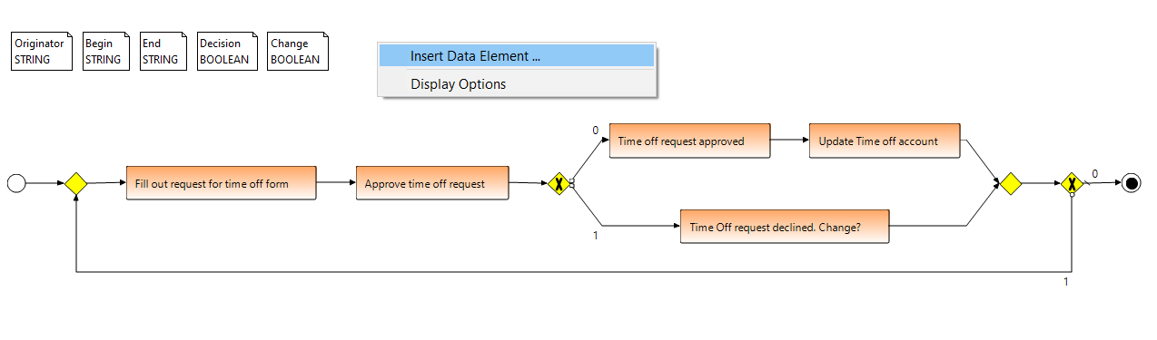
Create process data elements:
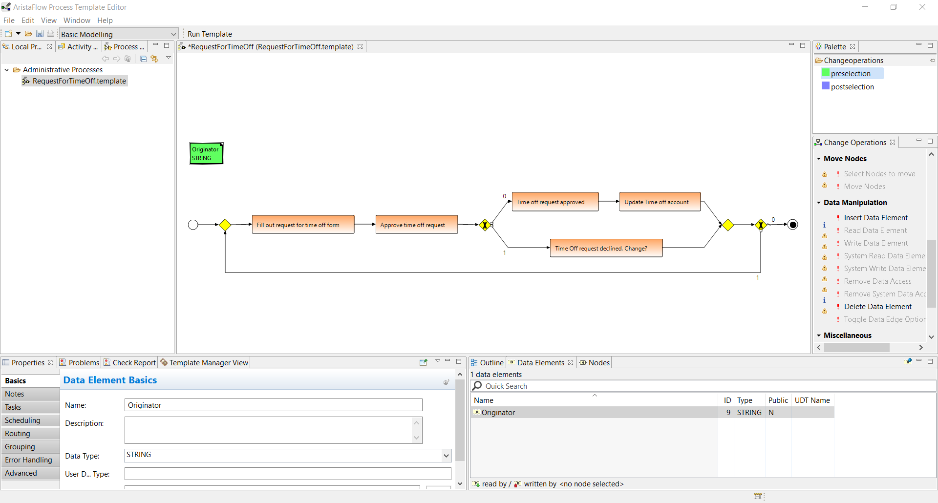
To create a new process data element select Insert Data Element in the Change Operations view. To change its properties select the data element and switch to the Basics tab of the Properties View. Alternatively switch to the Data Element View (in the lower right half of the editor) and select the data element value which you want to change.- For the process data element “Originator” create a new data element and set its Data Type to String*.
- For “Begin” and “End” create new data elements and set their Data Types to String as well.
- For “Decision” and “Change?” create a new data elements and set their Data Types to Boolean.
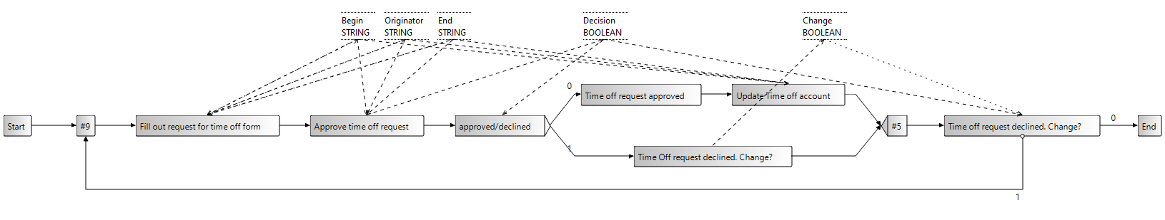
The result:
Hint:
To create a new data element simply right click over the graph into white area and select “Insert Data Element”. A Create new Data Element wizard opens in which you enter the name and choose the Type of the data element (see the last screenshot).
- For the process data element “Originator” create a new data element and set its Data Type to String*.
-
Model the data flow between the process steps:
To model the case that a process step delivers a data value you have to select the said process step as preselection and the data element where the data should be stored as postselection. Then select Write Data Element from the Change Operations View.
Example: Select the process step “Fill out request for time off form” as preselection and the data element “Originator” as postselection and push the Write Data Element button.
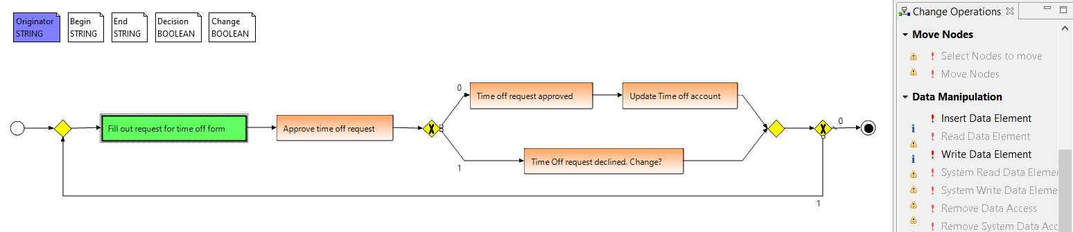
An arrow pointing towards the data element has been created.
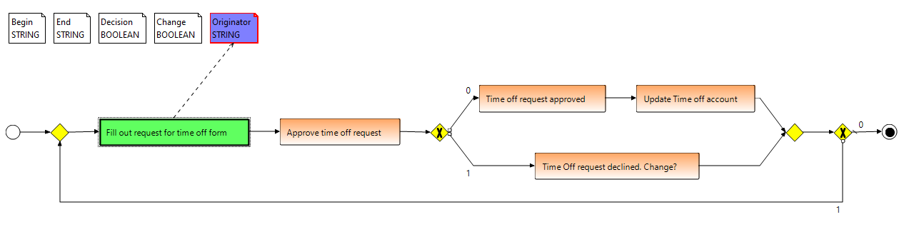
Similar to the delivery of data values you model the case that a process step needs data values for its execution. In this case select the data element as preselection and the said process step as postselection followed by a Read Data Element change operation.
Example: Select the data element “Begin” as preselection and the process step “Approve time off request” as postselection and push the Read Data Element button.
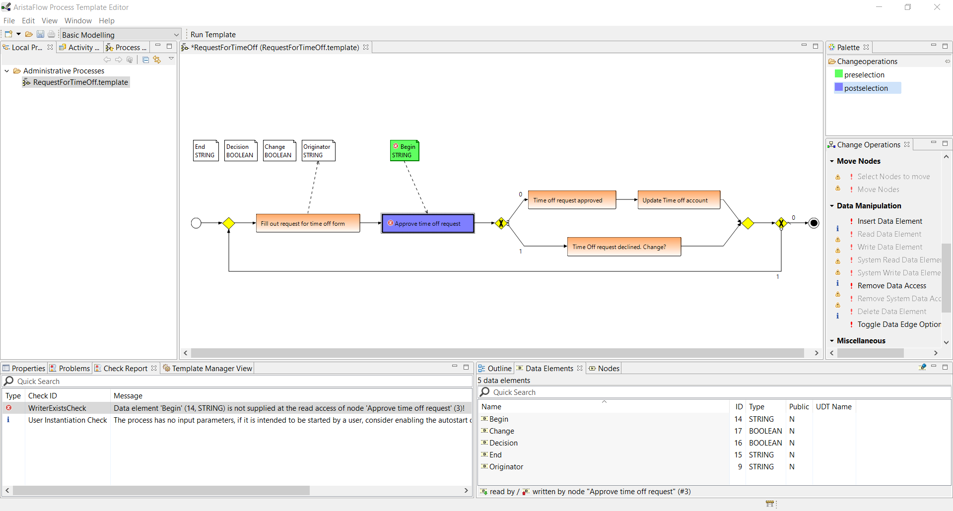
In the result you can see a red error symbol at the process step and the data element which is read by it. The Check Report View at the bottom informs us that no process step which is executed before the “Approve time off request” in the process flow delivers the “Begin” data element value. If we would try to execute this process it would definitely fail at runtime. The AristaFlow BPM-Suite checks those data flow errors on the fly no matter how complex the modeled processes are (including nested XOR-Blocks, sub processes etc.).
We fix this error by writing the data element from the “Fill out request for time off form”.
Hint:
To speed up the data flow modeling you can select more than a single data element or process step for read / write data edge operations by holding down the Ctrl. key during selection.
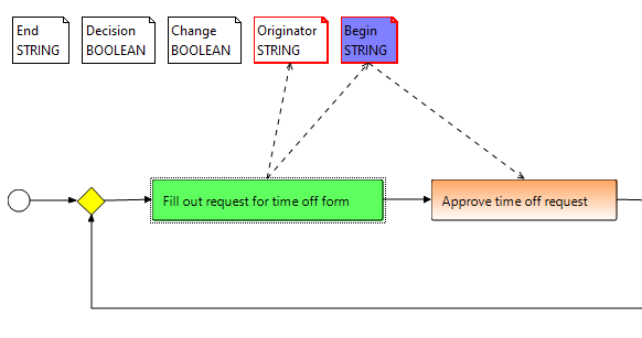
Complete the data flow in your process accordingly:- Process step “Fill out request for time off form”
Read (optional): “Originator“, “Begin“, End“
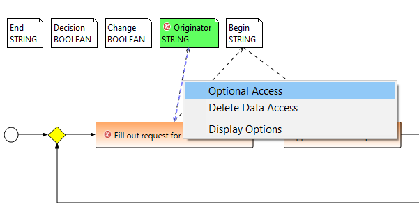
To read these three data elements is not essential but offers the possibility for the originator to see the data which he has filled in in the previous iteration. So it is much easier for him / her to correct the data. To prevent data flow errors you have to mark these read data edges optional, because in the first iteration of the loop they do not contain values.
Select the read data edges one by one and choose “Optional Access” in the right-click menu.
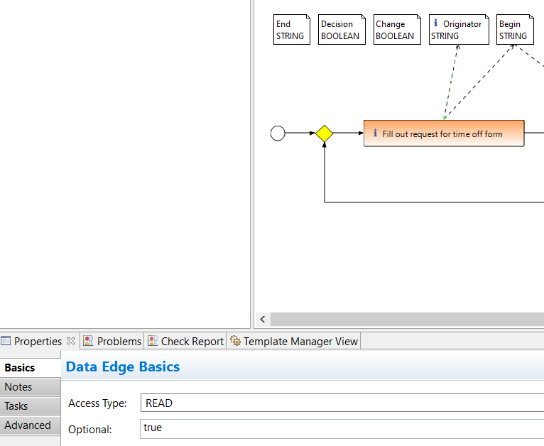
Alternatively after selecting the read data edge you change its Optional attributes to “true” in the Properties View.
Write: “Originator”, “Begin”, “End” - Process step “Approve time off request”
Read: “Originator”, “Begin”, “End”
Write: “Decision” - Process step “approved / declined”
Read: “Decision” - Process step “Update time off account”
Read: “Originator”, “Begin”, “End” - Process step “Time off request declined. Change?”
Write: “Change?” - Process step “Change time off request on decline?”
Read: “Decision”
Read (optional): “Change”
In this case it is necessary to set the read data edge to optional because a value is only delivered to “Change?” element if the request for time off was declined.
Result:
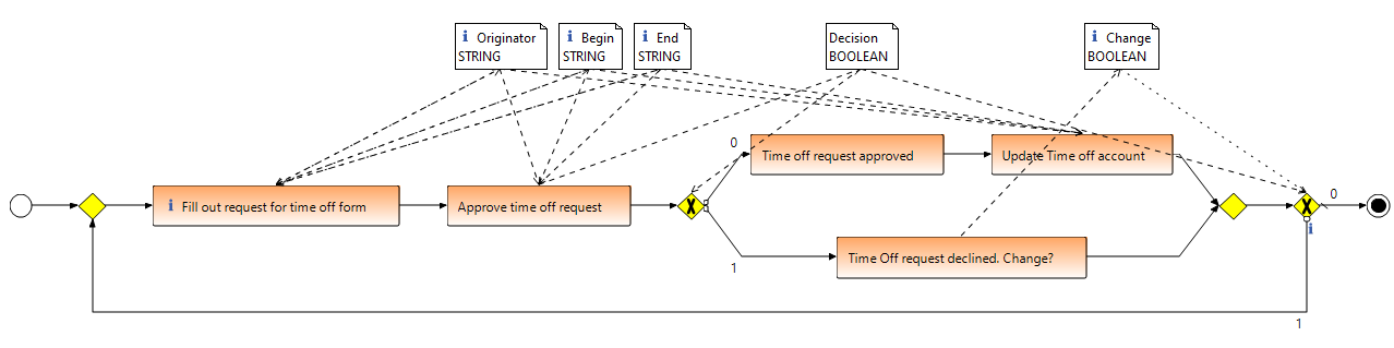
Result when using ADEPT symbols:
Hint:
For clarity reasons you can hide the data edges and / or the data elements. Right-click the working area of the editor and select Display options. Uncheck Data Edges Visible and / or Data Elements Visible in the upcoming dialogue. Furthermore you can check Dependency Visibility Mode to get a dynamic showing and hiding of the elements depending on the currently selected process step.
- Process step “Fill out request for time off form”