Process Template Editor
The Correctness by Construction paradigm
In contrast to all other process modeling tools you do not model your process graph only by drawing nodes and edges in the AristaFlow Process Template Editor, but also at the same time your model will be checked for correctness. The processes are designed by using a well defined set of process change operations like Insert Node or Delete Node to modify the process to your needs. By using these change operations it is guaranteed that the control flow model is valid at any point in time. Deadlocks, unreachable nodes or undefined process end points are automatically excluded. For business processes modeled with the AristaFlow Process Template Editor Correctness by Construction is guaranteed.
Overview of the modeling
In addition to the pure control flow of a business process we have to extend it with data or information which is exchanged between the single steps of a real life business process. Note that the creation of data flow offers another unique feature of the AristaFlow BPM-Suite. The on the fly correctness checks of data flows which is a part of the Correctness by Construction paradigm. With this feature we can guarantee that all services, forms, etc. which are assigned to process steps are provided with the data values they need for a correct execution at runtime.
The staff and activity assignments to the process steps also take place in the Process Template Editor. That means you determine in this tool who should carry out which tasks.
In AristaFlow we have a precise separation of process and application logic, so the activities/services are managed in a separate, versioned repository which is visualized in the Activity Repository Browser (the tab next to the AFResourceNavigator on the upper left side of the editor). Here you can find all components, functions and activities or more precisely activity templates which are available to be used in arbitrary business processes.
First, consider the following points before modeling a process:
- Which steps should the process go through
- What decisions and repetitions are there
- Which information is required or generated in which processsteps
- Which roles (agents) are involved in the process flow.
Overview Process Template Editor
First start the AristaFlow Server then the Process Template Editor. You can find more detailed information on starting the Process Template Editor under Start Tools.
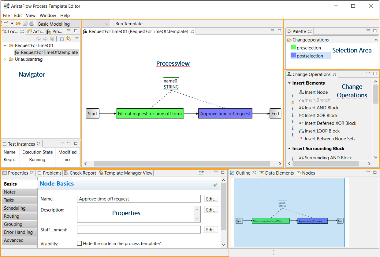
In the following you can see a summary of what is possible with the Process Template Editor.
- With the help of change operations, the control flow of the process can be represented as a directed graph
- This graph contains branches where decisions are made and which path to take next. For these decisions, data is required, which is generated in certain process steps with the change operations.
- Data is represented as data elements that are written or read by process steps. (Change Operations → Data Manipulation)
- The activities to be carried out are integrated into the corresponding process steps as plug and play applications (Navigator → Activity Repository)
- The staffs of the process steps are linked from an organizational model defined in OrgModelEditor. (Properties → Properties → Basics)
- Define several functions such as time management or escalation for the procedure for executing worklists. (Properties → Properties → Scheduling)
- Finally, the process is tested in the test client.
The created process templates can be saved as local template files or managed in a versioned manner after deployment on the server. (Properties → Template Manager View)
Draw process graph
To model a process using an example, see Modeling control flow in the Request for Time Off Tutorial.
-
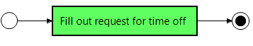
The modeling starts with an empty graph. At the beginning it only contains start and end nodes.
Note
With a right click on the process view (white area in the editor window) you can switch between ADEPT and BPMN symbols for the display via Display Options.
-
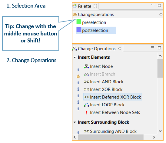
Changes are made via change operations, whereby the currently selected node determines the availability of the operation, e.g. insert node ...
- First select the area to change; the beginning with the preselection, the end with the postselection
- Then select the change operation
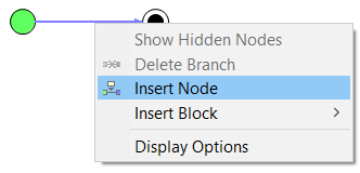
- Many changes are also possible via the context menu
→ Right-click on a process step or on an arrow between process steps, ...
→ ... opens a menu that offers context-sensitive possible changes (e.g. insert a new step at this point)
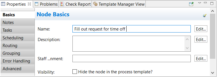
- The properties of the individual nodes can be customized using the Properties View.
→ Select a step with any selection
→ Activate the “Properties” view
→ Customize value
The new value is accepted withor when you leave the field. This also works with data elements and edges.
Alternatives, Repetitions and Parallelism (XOR, LOOP, AND)
- The process steps are not always sequential. In addition to sequences, alternative and parallel Sequences and loops can be modeled.
- Alternatives in the process
The process data determine the process flow. If some steps or step sequences are only to be carried out under certain conditions, this is modeled with an XOR block.
For example: Time off entry only if it has been approved
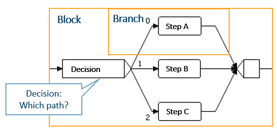
Either step A, B, or C is executed here.
Any number of branches and steps can be added. - Repetitions in the process
If certain steps or sequences of steps are to be repeated in certain cases, this is modeled with a LOOP block.
Example: If the application is rejected, change it and ask for approval again
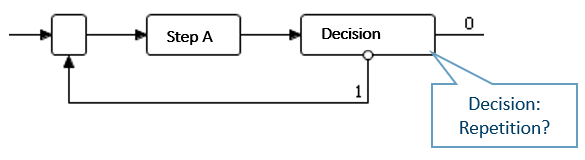
Step A is repeated here.
Any number of steps can be repeated. - Parallelism in the process
Simultaneous execution of mutually independent steps is modeled as an AND block.
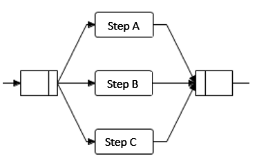
Here steps A, B, and C are carried out at the same time.
Any number of branches and steps can be executed at the same time. -
Decisions are made at two branches of these blocks, namely at the beginning of an XOR block or at the end of a LOOP block. These decisions must be made with the help of several data elements. When modeling, every possible case must be taken into account; a subsequent step must always be clearly selected. The user is guided by a wizard for correct modeling.
-
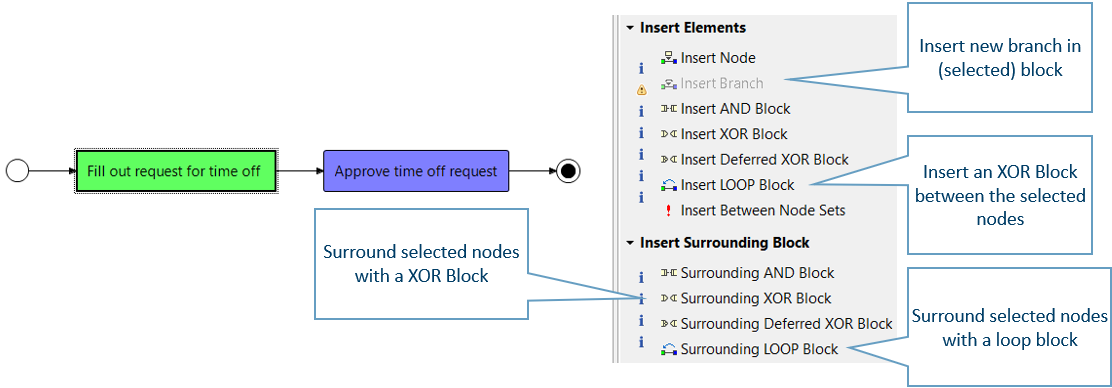
Inserting blocks
With various change operations you can insert all possible blocks by selecting block start and end- Insert block between nodes → Insert XOR Block
- Surround part of the process with a block → Surrounding XOR Block, Loop Block ...
- Insert new branch between two block nodes → Insert Branch
Process data
To model the process data using an example, see Modeling data flow in the time off request tutorial.
- Data is stored in data elements (variables) by storing the name and type
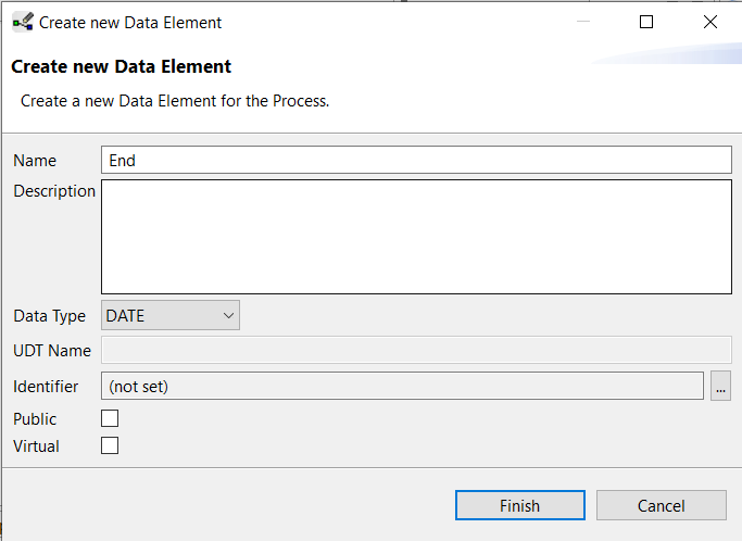
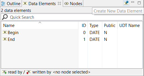
- Insertion of data elements via change operation or via the Data Elements view (in the lower right corner of the editor)
→ Create New Data Element via the toolbar of the view
Some properties of the data elements can also be changed directly here.
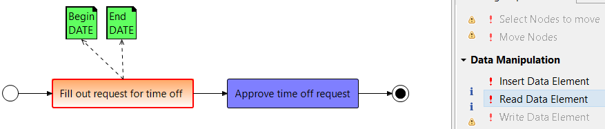
- Process steps can write or read data elements
- Reading and writing of data elements via selection and change operation
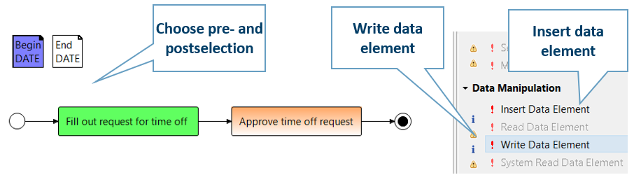

-
Access to data elements can be represented graphically with arrows
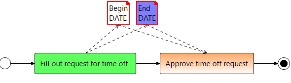
Fill out request for time off writes Begin and End of time off.
Approve time off request reads in this data -
Multiple read/write accesses can be changed at once Keep the Ctrl key pressed during the selection Several data elements as preselection + one node as postselection → read several data elements
-
Data flow check: It is checked whether data is available exactly when it is required by a step.
AristaFlow BPM Suite checks the data flow and reports problems in the Test report tab (another tab in the Properties view) Important element for robust process control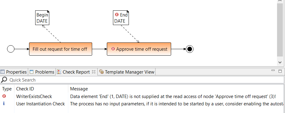
Optional Data
If a data element has not been written, it cannot be read either. This is the case, for example, with voluntary information. Make the data access optional so that read access to a data element that has not yet been written does not trigger an error or write access to a data element can take place voluntarily.
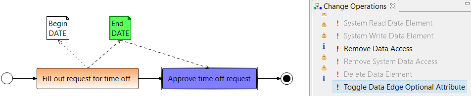
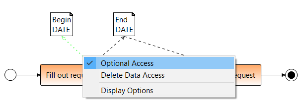
Optional data edges can be created via the change operation Data manipulation or Properties or the context menu of a selected data edge.
- Choose first the pre- and postselection and then the change operations Toogle Data Edge Optional Attribute
- Select the data edge and right click on the edge
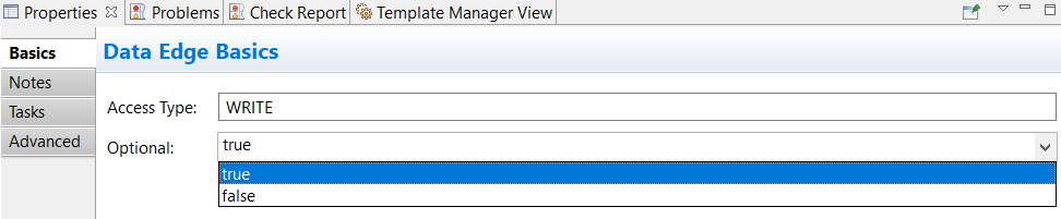
- Select the data edge and set under Properties Basics → Optional to true.
Available Datatypes
| Typ | Values | Example |
|---|---|---|
| STRING | String | „Text“ |
| INTEGER | Ganzzahl | 4711 |
| DATE | Datum | 21.12.2018 13:30:04 |
| BOOLEAN | true / false | false |
| FLOAT | floating point number | 47,114711 |
| URI | Ressource | file:/c:/MyTable.xls |
| USERDEFINED |
- USERDEFINED: User-defined type
Additional field: Designation for the type
Usage: Binary data of any size
Example: Documents, images, PDF files, …
Insert activities from the Activity Repository
With the ARISTAFLOW Activity Repository, ARISTAFLOW offers a powerful tool to integrate almost any activities, functions and services into a process. The appropriate application is installed from the Activity Repository via drag'n'drop on the desired node in the process. Depending on the type of activity, wizard pages can be used to change the properties (name, description) of the activity or to assign the parameters (data elements) as input or output of the activity. All activities/services are reusable and are constantly being developed.
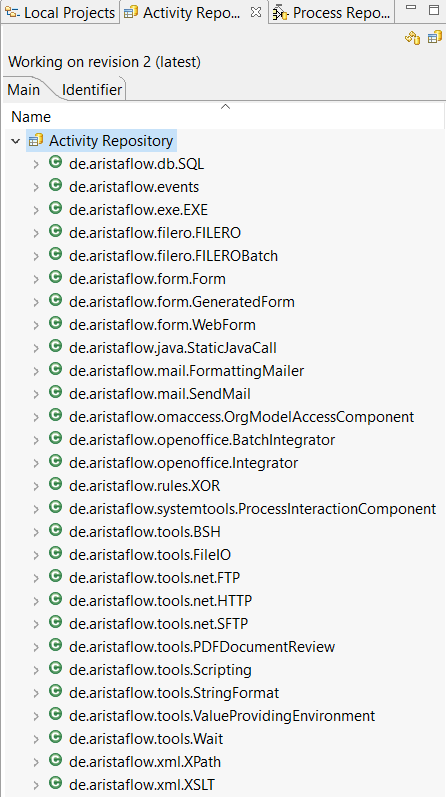
Overview of existing activities
-
Interactive activities with surface These activities require user interaction like forms. Different types of forms are available.
- WebForm with Form Designer
- User Form for user forms
- Generated form with images for quick prototyping
-
Automatic activities These activities are carried out after modeling by the Automatic Client.
- Database connection (any SQL databases): de.aristaflow.db.SQL
- Calling binaries (e.g. EXE files): de.aristaflow.exe.EXE
- Calling Java methods: de.aristaflow.java.StaticJavaCall
- Email dispatch: de.aristaflow.mail.SendMail
- FILERO Batch (integration of FILERO, an enterprise information management system): de.aristaflow.filero.FILEROBatch
- Access to organizational model: de.aristaflow.omaccess.OrgModelAccessComponent
- Process control (e.g. for error handling): de.aristaflow.systemtools.ProcessInteractionComponent
- XOR predicates: de.aristaflow.rules.XOR
- Execution of scripts: de.aristaflow.tools.Scripting
- File operations: de.aristaflow.tools.FileIO
- FTP, SFTP Upload: de.aristaflow.tools.net.FTP, de.aristaflow.tools.net.SFTP
- HTTP requests (GET, POST): de.aristaflow.tools.net.HTTP
- Text formatting with process variables (string formatting): de.aristaflow.tools.StringFormat
- Waiting for a certain time, for a point in time: de.aristaflow.tools.Wait
- Evaluation of XPath expressions: de.aristaflow.xml.XPath
- XML transformations using XSLT: de.aristaflow.xml.XSLT
- ...
User Form
End user forms can be integrated into a process step as follows:
Drag and drop the User Form activity onto the desired node and release it. This activity is recommended for all interactive steps. In the time off request tutorial, you can understand the assignment of activities using an example.
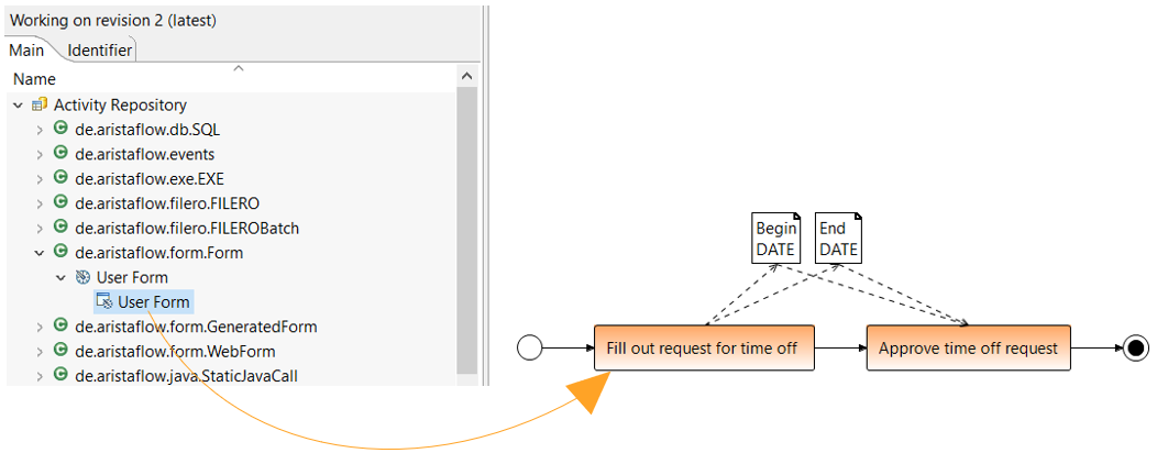
- Name and describe the activity in the first Wirzard page.
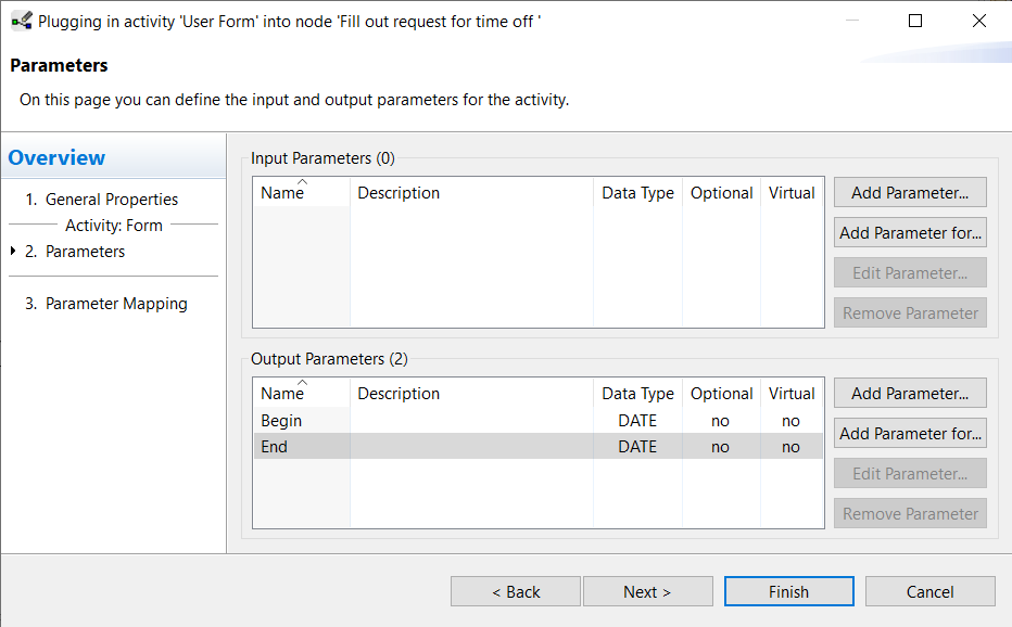
- Then map input and output parameters:
- Modeled data flow is adopted as a parameter → an input/output parameter is generated for every read/write access with plug and play.
- Check input and output parameters and add them if necessary.
Input parameters are the data elements that are displayed in the form.
Output parameters are the data elements that the user writes.
XOR Predicate
The decision at the beginning of an XOR block is executed by Automatic Client. For this, however, the activity XOR Predicate must be integrated and modeled as follows:
- The appropriate activity XOR Predicate can be found in the Activity Repository Browser under de.aristaflow.rules.XOR and embedded on the XOR node.
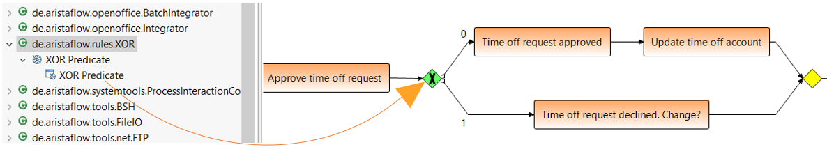
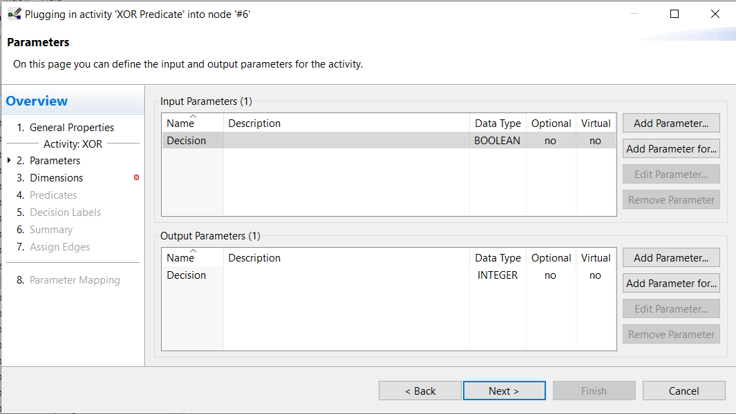
- Properties can then be adjusted in the wizard.
At least one input parameter is necessary for a decision. The system uses Decision as output parameter by default.
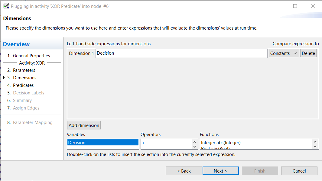
- A dimension is required for each decision parameter. To add a dimension double-click on the variables in the list at the bottom of the wizard window.
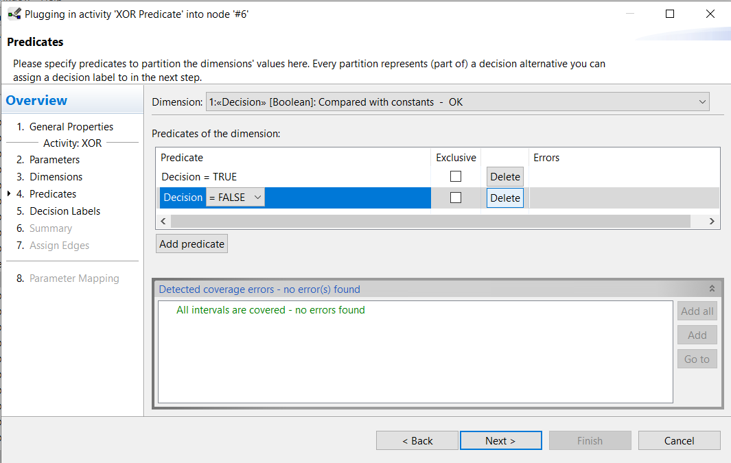
- All possible values for this parameter (dimension) are entered. Select Add all (in the lower right corner of the wizard window) to complete the values for the dimension. Or click Add predicate to choose the values for the dimension.
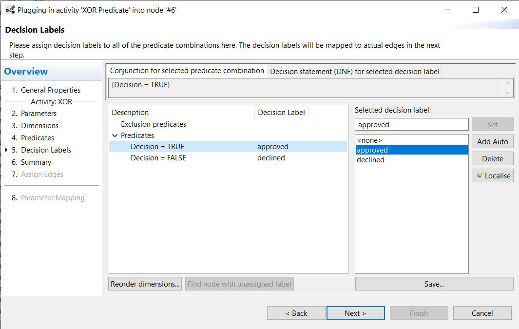
- A decision ID is assigned to each predicate. Select a predicate and click the Add Auto button to create an ID automatically or enter your own ID in the input field and choose Set.
- At Assign Edges the decision IDs are linked to the outgoing edges of the XOR node. Select the decision ID and the edge and connect them by clicking the arrow button in the middle of the wizard window.
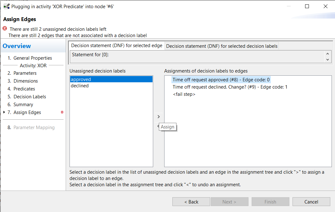
For more information on setting XOR Predicate, see Request for Time off -> Assign activities.
Execution in the Test Client
Test Client allows the local execution of processes without having to upload the template to the AristaFlow Server. It is an important tool to check how the switching behavior of the process is and whether each step is getting the expected data. The integrated activities are also tested, but without taking the staffassignment into account. Because when executing in the Test Client, each step is explicitly started and executed by the modeler (including the steps of automaticclient). The Test Client enables the process to be executed early without full modeling. In the Tutorial Request for Time off you can see how a process template is tested step by step.
Requirements for testing a process template:
- Decisions for blocks (XOR, LOOP) have to be modeled
- Execution on Test Client exams must be completed successfully
- The exams can be selected via the toolbar of the Process Template Editor.
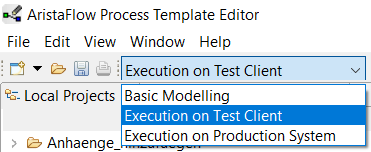
To start the test client, click on Run Template at the top of the editor. You can find more information in Installation and Configuration -> Start Tools.
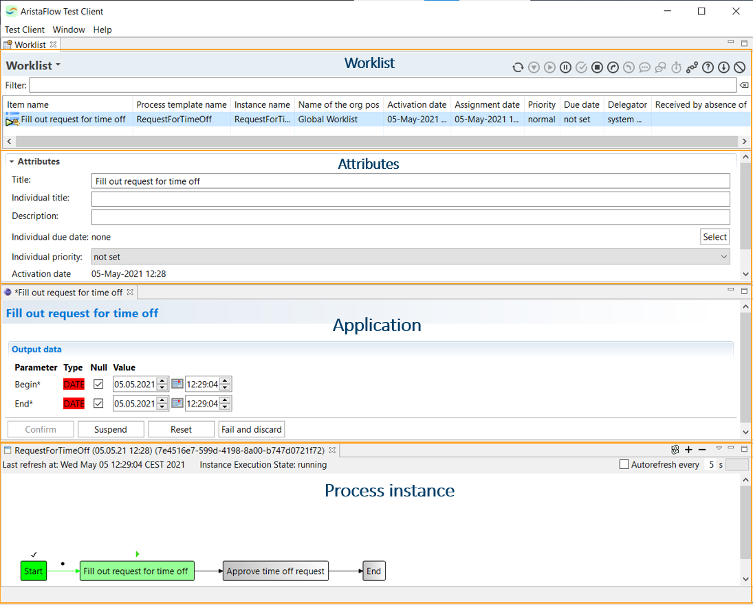
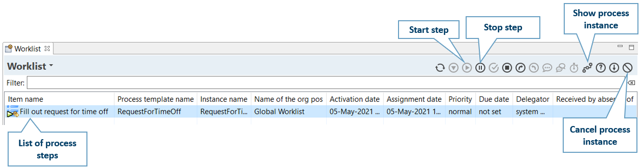
Overview test client
Connection of organizational model
Staff Assignment Rule
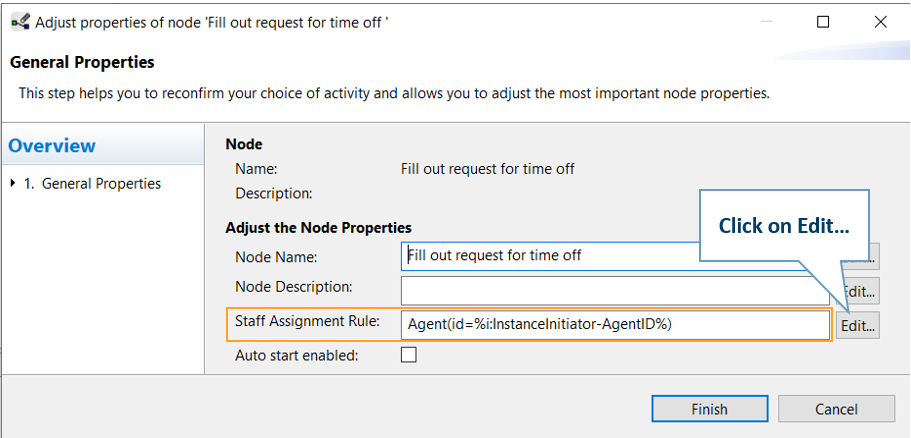
The assignment of agents to the process steps is based on certain rules. The wizard pages for this assignment can be reached via node properties or the plug-and-play wizard. You can get a step-by-step implementation of the Staff Assignment Rule at Tutorial Request for Time off -> Staffassignment.
- Single click on node → Properties view → Basics → Staff Assignment → Click on Edit...
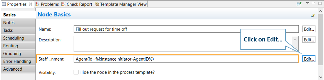
- Double click on node Staff Assignment Rule → Click on Edit...
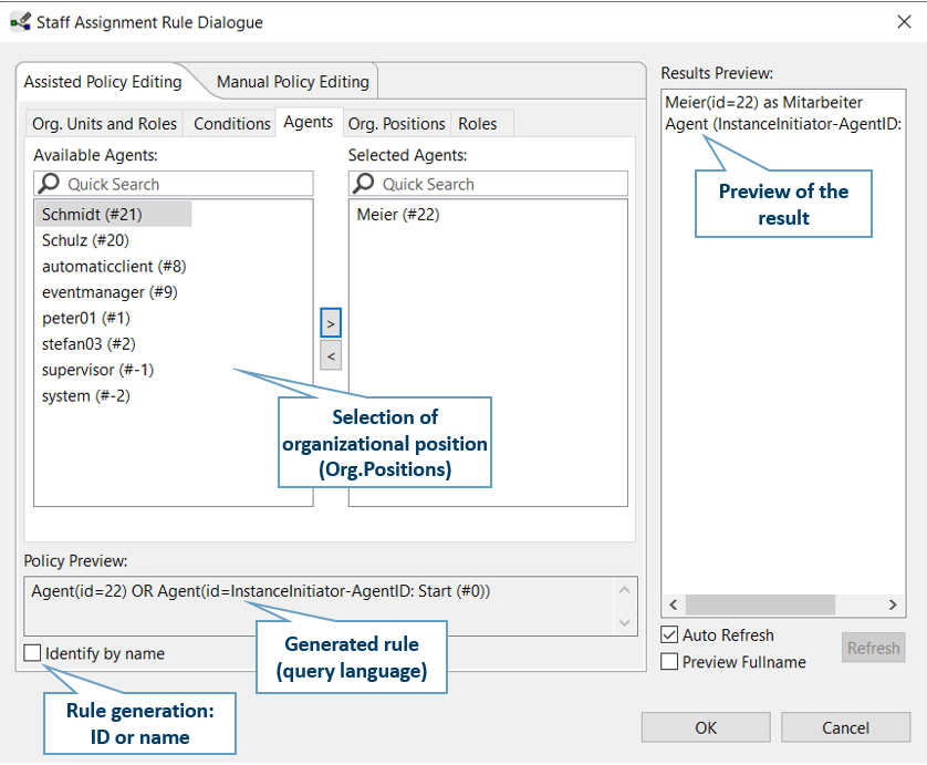
The assignment can be selected as follows from the defined organizational model in the Assisted Policy Editing tab or entered manually in the Manual Policy Editing tab.
Agent assignment - Assisted
In this tab you can select the agents from the list according to OrgUnits, OrgPositions and user names (agents) or roles. You can also consider dependencies between process steps when choosing the agents. The assignment is made using the arrow button in the middle of the wizard window. For more information see Tutorial Request for Time off -> Staffassignment.
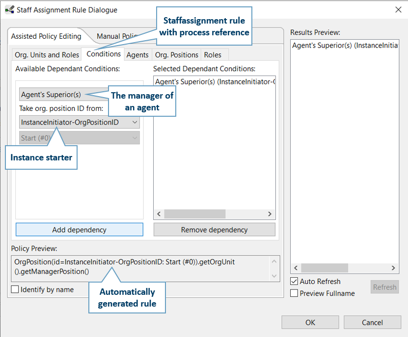
 For staff assignment rule with process reference, select the Conditions tab. When a process instance is executed, the ID of assigned agent and its OrgPosition ID are recorded internally for each step. This makes it possible to commission the manager of the previous assigned staff for a later step as the staff to assign, for example.
Note
Automaticclient must be assigned as the staff for the decisions in the case of XOR or LOOP block..
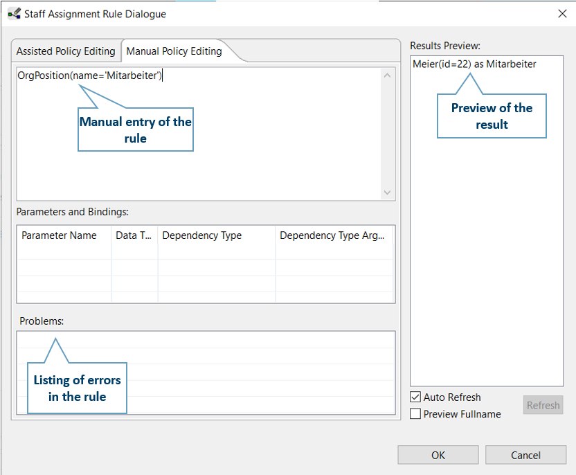
Agent assignment - Manual
You can enter the editing formula manually in the Manual Policy Editing tab.
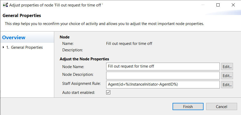
Use of auto start
With the activation of Auto start the process step is started automatically in the client of the user. This function is available for all process steps, but only for certain dependent staff assignment rules. In the first step, this is the case if the instance starter is the assigned agent. This is achieved by selecting InstanceInitiator as Agent ID in the SAR dialog. In the case of autostart in other steps, the dependency NodePerforming-AgentID, i.e. the agent assigned to the previous step, must be selected.