Modeling control flow
Model the individual process steps
Start the AristaFlow Process Template Editor from the Windows start menu under ...AristaFlow BPM Suite -> Process Template Editor or in your installation folder under (…\ProcessTemplateEditor\ProcessTemplateEditor.exe).
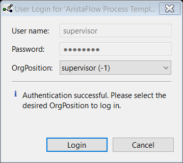
Authenticate with a valid user name and password in the upcoming login dialogue (initially supervisor / password).
After login you enter the AristaFlow Process Template Editor where you can design arbitrary business processes of your company.
For the creation of a new process template the following steps are necessary:
-
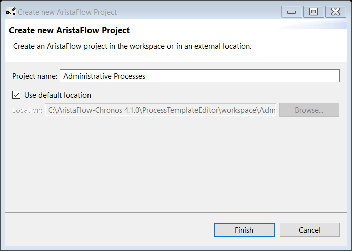
At first you have to create a new AristaFlow project. Right-click in the white area under the Tab Local Projects in the AFResourceNavigator view which you can find in the left upper corner of the Process Template Editor. Select New -> AristaFlow Project and enter Administrative Processes. Close the dialogue.
-
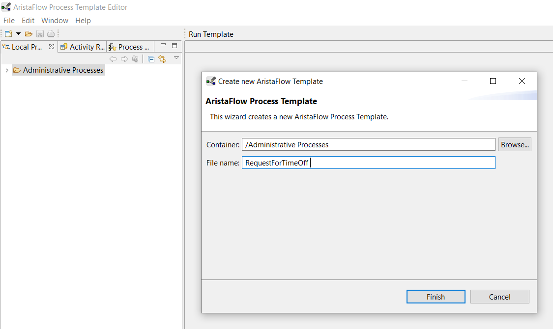
Now create the new process template. Right-click the newly created Administrative Processes project and select New ->AristaFlow Template. Enter RequestForTimeOff in the File name input field of the dialogue and press finish.
 What you can see now in the working area of the Process Template Editor is the starting point for the design of every new business process: A single Start and its related End process step (in the following we sometimes use the simple term node as substitution for process steps).
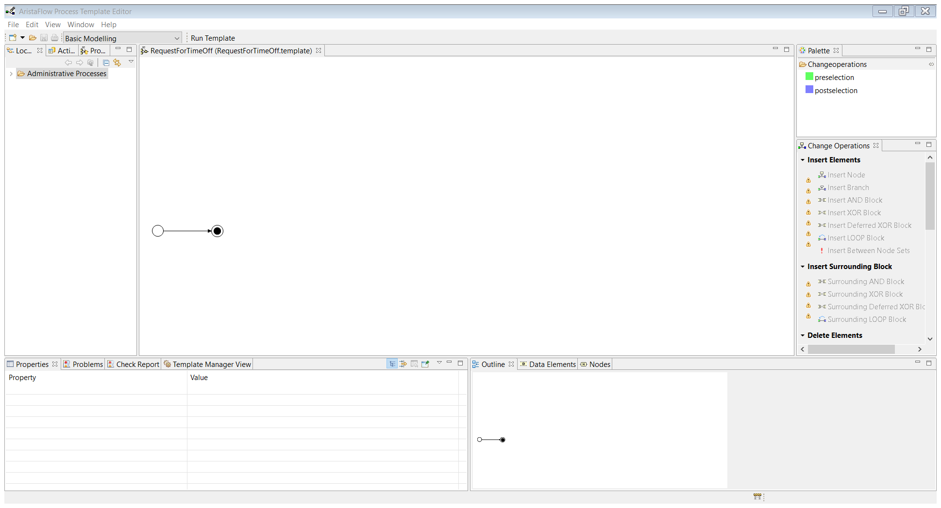 Now you can start to modeling the control flow of the process (process routing)
Now you can model your control flow.
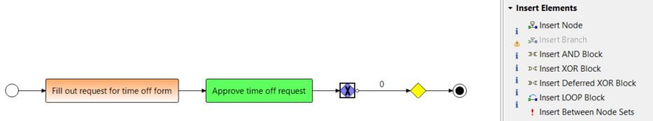
- More precisely the control flow of a process model is designed by selecting a pre- and postselection (preselection and postselection in the upper right corner under Change Operations) followed by the selection of an enabled change operation on the right side of the editor. For example: Insertion of the first step “Fill out request for time off”. Select the Start node in the preselection mode. The Start node turns green. Switch to postselection and select the End node. The End node turns blue.
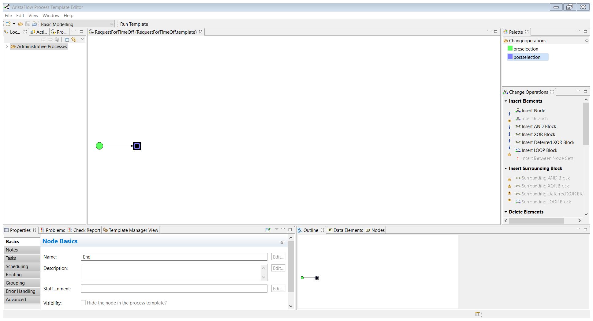
As a result of the selection exactly those change operations are enabled in the Change Operations View (on the right side) which can be applied in the given context without destroying the correctness of the process graph.
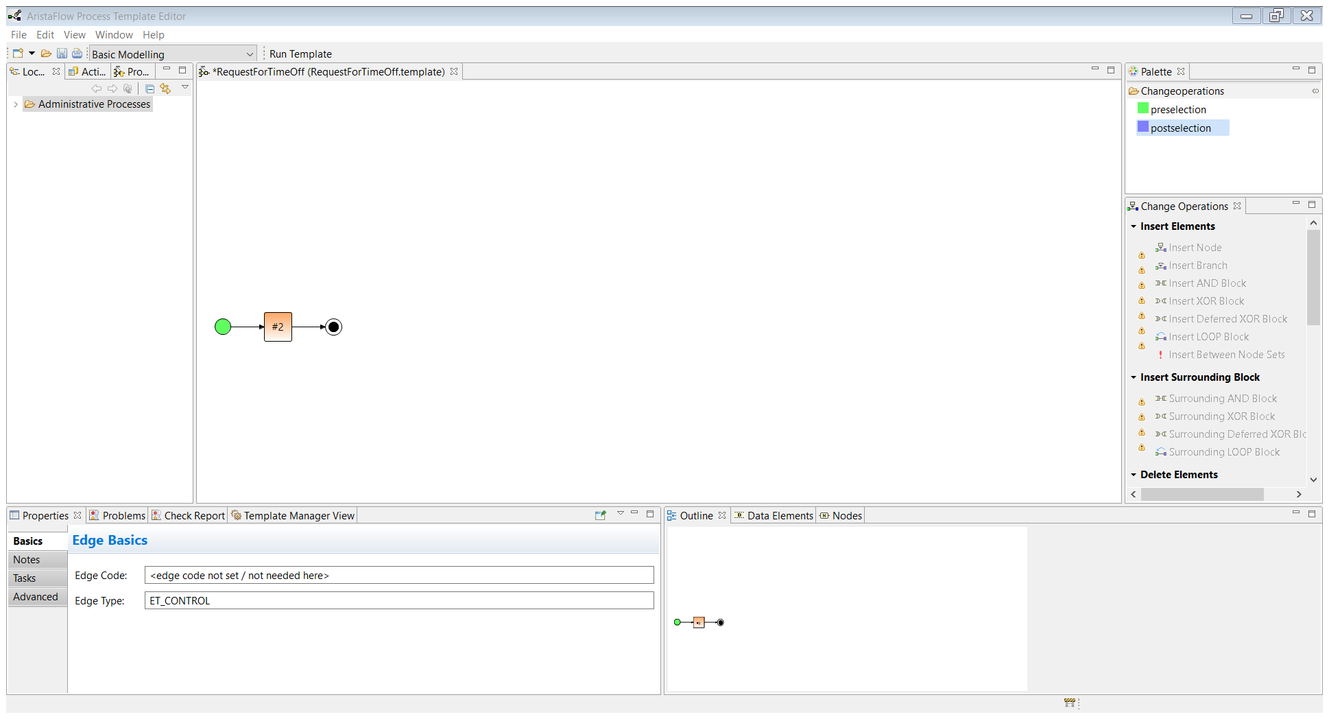
Select Insert Node and you can see that a new process step has been inserted automatically between the nodes of the pre- and postselection.
Hint:
Instead of the explicit selection of the pre- and postselection in the upper right corner you can switch between the selections by using the middle mouse button.
Hint:
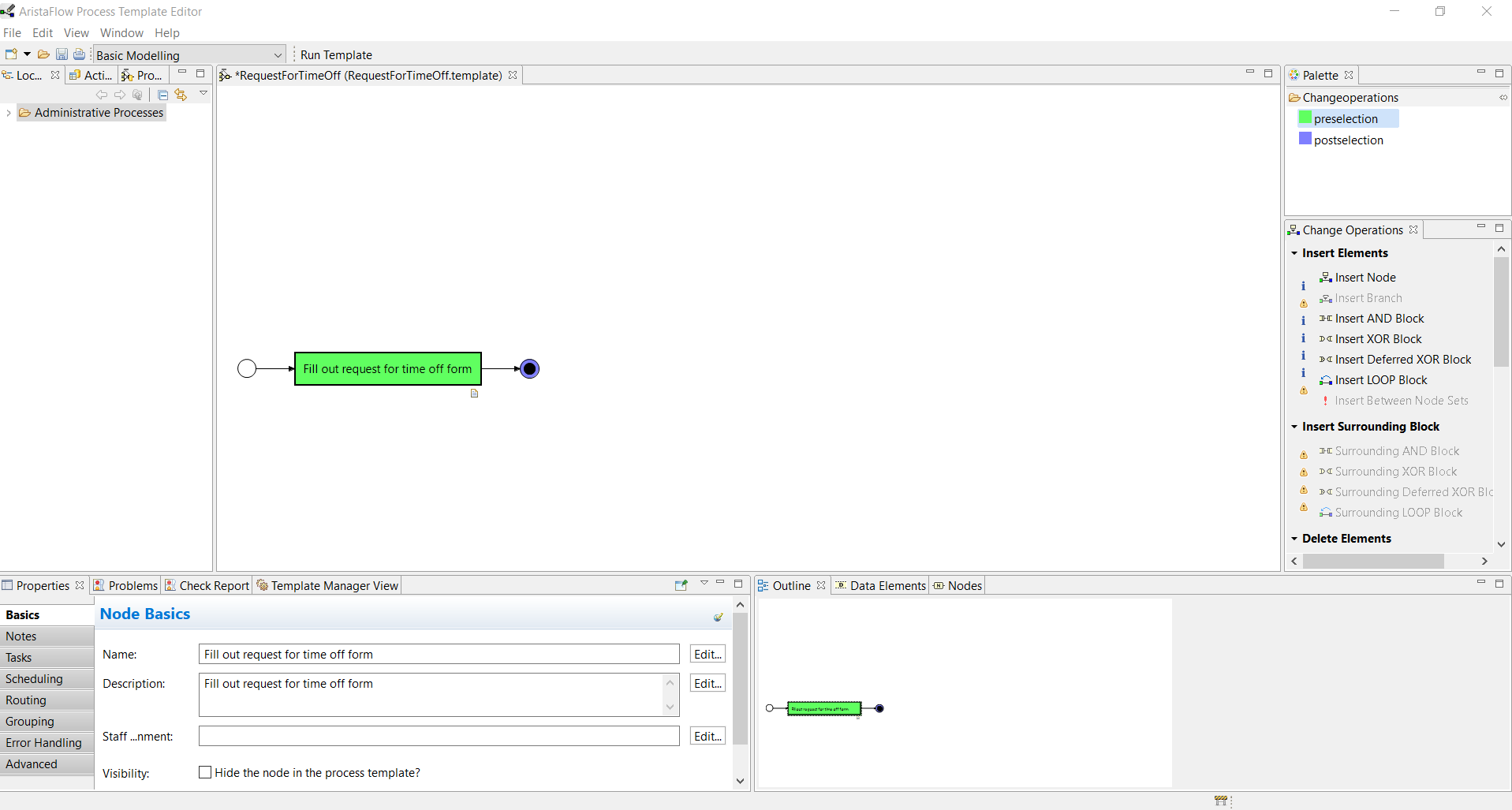
Tooltips on disabled change operations give information about the reason why there are not applicable in the given context. - To change the properties of a process step select the Properties View (bottom left). On the left hand side of the properties view you can see a couple of further tabs which groups the properties according to their functions like scheduling, error handling, routing, and so on.
For now the Basics tab is sufficient for our needs. Select the newly inserted node #2 and fill in the label of the node in the Name input field (“Fill out request for time off form”).
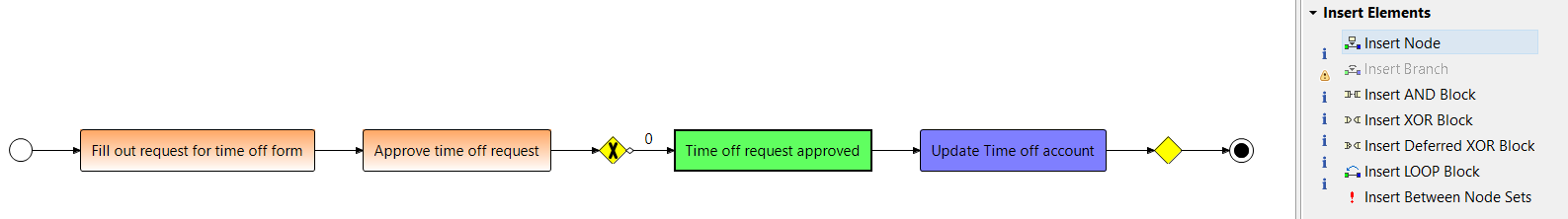
- Design the next process step according to the explanations given in 1. and 2. and name it “Approve time off request”. After this node the request will be either approved or declined. This branch requires an XOR node. You can do this by “Insert XOR Block” in the Change Operations View and call it “approved/declined”.
- On this branch you add the two nodes “Time off request approved” and “Update Time off account” according to 1. and 2.
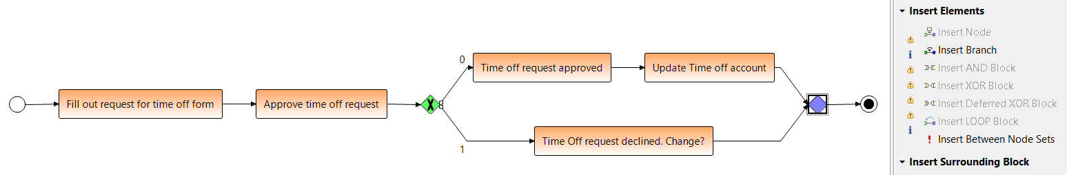
- If the request is declined you need to add another branch by “Insert Branch” in the Change Operations View. On this branch you map the node “Time off request declined. Change?”.
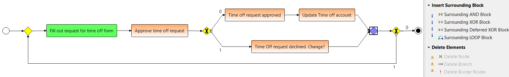
- In case of another request the workflow should go back to the start. You can do this Loop-Block with a “Surrounding LOOP-Block” over the first node “Fill out request for time off form” (as preselection) and the last XOR-Join node (as postselection). As name enter “Change time off request on decline?”.
The final result should look like this:
Hint:
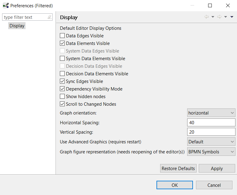
Note that you may use BPMN symbols or Adept Symbols in the process model. In this example BPMN Symbols were used. To do that, right-click the working area of the editor and select Display options. Then, choose BPMN Symbols for Graph figure representation in the Display options window.